Manufacturing processesReading time 13 min
How cutting conditions actually get decided
The same tool, the same machine, the same material, and two machinists will set parameters twice apart, and both will produce good parts. The difference is what each is optimising for.
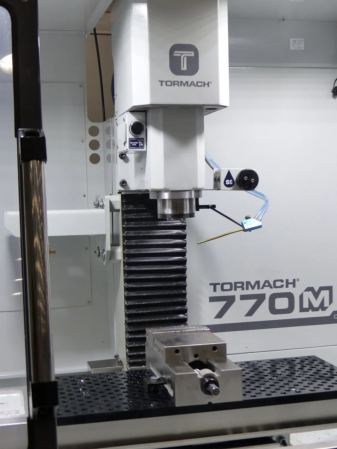 Wikimedia Commons・CNC Mill 1.jpg・CC BY-SA 4.0
01Three parameters, three formulas
| Parameter | Symbol | Formula | Decides |
|---|---|---|---|
| Cutting speed | Vc (m/min) | Vc = π × D × n ÷ 1000 | Tool life, cutting temperature |
| Spindle speed | n (rpm) | n = Vc × 1000 ÷ (π × D) | Derived from Vc |
| Feed per tooth | fz (mm/tooth) | fz = Vf ÷ (n × z) | Chip thickness, finish, chip breaking |
| Feed rate | Vf (mm/min) | Vf = fz × z × n | The value actually sent to the machine |
| Axial depth of cut | ap (mm) | — | Productivity, axial force |
| Radial depth of cut | ae (mm) | — | Radial force, vibration, engagement angle |
Material removal rate, MRR = ap × ae × Vf ÷ 1000 in cm³/min, is the single measure of productivity. But the same MRR can be reached with a deep cut and slow feed or a light cut and fast feed, and the two behave completely differently towards the tool, the machine and the workpiece.
02Get Vc wrong and tool life changes several times over
The relationship between tool life and cutting speed is described by Taylor's equation: Vc × T ⁿ = C, where T is life and n depends on the tool material (about 0.1 for HSS, 0.2–0.3 for carbide, 0.4 and above for ceramics). A small exponent means life is extremely sensitive to speed: raise Vc by 20% on a carbide cutter and life may halve.
| Materials | Carbide end mill Vc (m/min) | Notes |
|---|---|---|
| Aluminium 6061 | 300 ~ 1000 | Built-up edge is the enemy, so speed should be high |
| Low-carbon steel S45C | 120 ~ 200 | The usual benchmark |
| Stainless SUS304 | 80 ~ 140 | Work-hardens badly; the cut must not be too light |
| Cast iron FC250 | 100 ~ 180 | Chips break well but it is abrasive |
| Titanium Ti-6Al-4V | 30 ~ 60 | Poor conductivity; the heat stays in the edge |
| Hardened steel HRC50+ | 50 ~ 120 | Needs CBN or ceramic tooling |
03Feed per tooth: too small is worse than too large
Intuitively a small feed means a better finish and less risk. It does not. When feed per tooth falls below the edge radius, the edge cannot enter the material and simply ploughs through it, generating a great deal of friction heat, wearing the edge quickly and leaving a worse finish. This is the ploughing effect.
- Lower limit. fz should not fall below the cutting edge radius, generally 0.02 to 0.05 mm.
- Upper limit. Set by tool strength, machine power and the surface finish required.
- Surface finish. In turning the theoretical value is Rz ≈ f² ÷ (8 × nose radius), so a larger nose radius gives a better finish at the same feed.
Chip thinning
In milling, when the radial depth ae is less than the tool radius the actual chip is thinner than fz, roughly by √(ae/D). So in high-speed machining, with small ae and large ap, fz has to be increased to keep the effective chip thickness up, otherwise you are back to ploughing.
04Depth of cut: productivity against vibration
| Strategy | ap | ae | Where it fits |
|---|---|---|---|
| Conventional milling | Small (0.5–2 mm) | Large (0.5–1 D) | Ordinary machine rigidity, roughing |
| High-speed machining | Large (1–2 D) | Small (5–10% D) | Rigid machines, deep pockets, hard material |
| Trochoidal | Large | Small, on a looping path | Slotting, avoiding full engagement |
The usual symptom of the wrong strategy is chatter. Chatter comes from the cutting force frequency approaching a natural frequency of the system, and the fix is not necessarily to slow down, sometimes it is to speed up past the resonance, or to change ae so the tooth entry frequency shifts.
05Why following the catalogue still goes wrong
- Catalogue conditions assume a rigid machine. An older machine, a long tool holder or a thin-walled part all force the usable parameters well down.
- The coolant does not match. The same tool has a completely different Vc ceiling dry, with air, or with soluble coolant. Some coatings chip from thermal shock if flooded during interrupted cutting.
- Overhang gets ignored. Double the tool stick-out and deflection increases roughly eightfold, it is a cubic relationship.
- How the part is held. A parameter set that runs happily in a vice can push the part straight off a vacuum chuck.