Automated inspectionReading time 12 min
Whether machine vision can see it is half decided by the lighting
When a vision system will not work, engineers usually blame the algorithm first. The real cause is normally further upstream: in the image, the defect simply is not obvious.
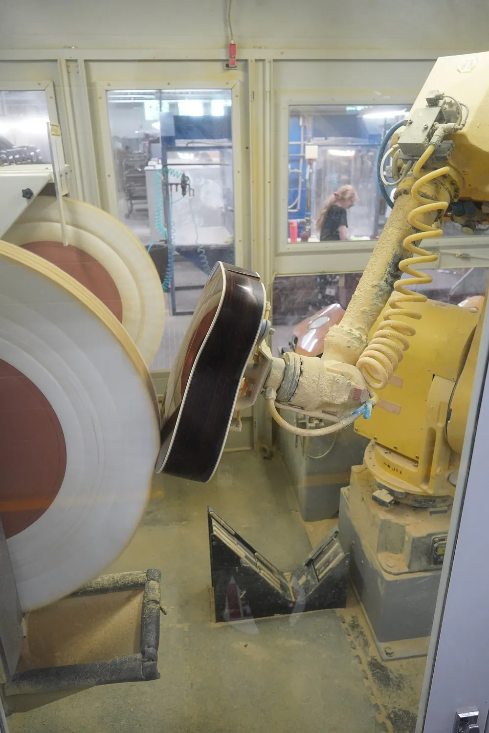 Wikimedia Commons・Robotic Arm Polishing Guitars at Martin Guitar・CC BY 4.0
01Calculate first, then talk about seeing
The first design step for a vision system is resolution. The formula is simple: real size per pixel = field of view width ÷ horizontal sensor pixels.
| Item | Example | What it asks |
|---|---|---|
| Field of view | 50 mm | The area you need to see |
| Sensor | 2448 × 2048 (5 megapixel) | Camera specification |
| Spatial resolution | 50 ÷ 2448 ≈ 0.020 mm/px | How much one pixel covers |
| Detectable defect | About 0.06 to 0.1 mm | Usually needs 3 to 5 pixels to be reliable |
| Measurement accuracy | About 0.005 to 0.01 mm | Sub-pixel algorithms reach 1/4 to 1/2 pixel |
02Lighting decides everything
The same part under different lighting can produce completely different images. The principle is simple: make the feature you are looking for brighter or darker, and keep everything else uniform.
| Technique | Arrangement | Good at finding |
|---|---|---|
| Backlight | Source behind the part | Outline, through holes, missing parts |
| Coaxial | Light through a beam splitter, on the lens axis | Scratches on mirror surfaces, printed characters |
| Ring light (high angle) | Angled down from around the lens | Surface texture, general appearance |
| Low-angle ring light | Almost parallel to the surface | Engraving, relief, edge chips |
| Diffuse dome | Diffuse reflection off a hemisphere | Even lighting on curved or shiny parts |
| Structured light | Projected fringes or a line laser | Three-dimensional height, flatness, volume |
Wavelength is a variable too
Red penetrates further but gives poor contrast on red features. Blue is shorter and scatters less, suiting fine features and precise measurement. Infrared passes through some plastics and shows what is inside. Ultraviolet excites fluorescence, useful for checking adhesive volume and coating coverage.
03Four common applications
- Presence and absence. Is the part there, is it the right way round. The simplest, most stable and highest-return application.
- Dimensional measurement. Outline, hole diameter, spacing. Needs accurate lens calibration and a repeatably positioned part.
- Appearance inspection. Scratches, dents, contamination, colour variation. The hardest, because defects vary so much in form.
- Character and code reading. OCR, barcodes, DataMatrix. Mature technology; lighting and contrast are what matter.
Roll them out in that order. Start with presence and absence, get the optics, mechanics, triggering and data flow running smoothly, then move towards appearance inspection. Doing it the other way round usually stalls at the first hurdle and gets abandoned.
04Three questions to ask first
- Can you write down the definition of the defect? If your own experienced inspectors do not agree with each other, no system will be consistent either. Run a repeatability study on human judgement first, much like GR&R.
- Can you control how the part sits? Nothing hurts a vision system more than variable position and attitude. Most failed projects fail on mechanics, not software.
- What does each kind of error cost? The cost of a miss and the cost of an over-reject are usually not symmetric, and the threshold should lean towards whichever is cheaper.