Machine elementsReading time 13 min
How to read the parameter table in the corner of a gear drawing
The circle drawn on a gear drawing is not the real shape of the gear. What decides whether it will mesh with another gear is the table in the corner.
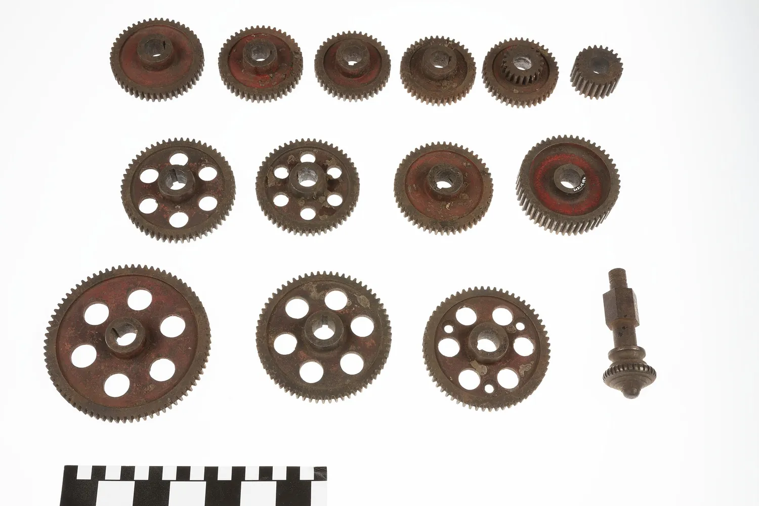 Wikimedia Commons・One Knobbed Gear Shaft and Thirteen Spur Gears・Public domain
01Why the tooth profile is not drawn
An involute profile is a mathematically defined curve. Drawing it is neither accurate nor useful, because the teeth are generated by a hob or shaper cutter rather than cut to a line. So drafting standards call for a simplified representation: the tip circle as a solid line, the pitch circle as a thin chain line, the root circle as a thin solid line or omitted, with the real specification written in the parameter table.
02The core fields of the table
| Parameter | Symbol | Meaning |
|---|---|---|
| Module | m | Pitch diameter ÷ tooth count; sets the size of the teeth |
| Number of teeth | z | How many teeth in one revolution |
| Pressure angle | α | The reference angle of the involute; 20° is standard |
| Tooth system | — | Full depth or stub; sets the addendum coefficient |
| Profile shift coefficient | x | How far the cutter is moved relative to the pitch circle |
| Pitch diameter | d | d = m × z |
| Tip diameter | da | da = m(z + 2) for a standard spur gear |
| Root diameter | df | df = m(z − 2.5) for a standard spur gear |
| Span measurement / measurement over pins | W / M | The dimension actually accepted |
| Accuracy grade | — | Grade 6 or 7 to ISO 1328, for example |
03Centre distance and ratio
For two standard gears the centre distance is a = m(z₁ + z₂) / 2 and the ratio is i = z₂ / z₁. Simple enough on paper, but in practice the centre distance is usually fixed by the mechanism while m and z must be particular numbers, and that is where profile shift comes in.
Profile-shifted gears
Profile shift moves the cutter outward or inward relative to the pitch circle, changing tooth thickness and profile. It serves three purposes: making a non-standard centre distance work, avoiding undercut on small tooth counts (below z = 17 at a 20° pressure angle), and balancing root bending strength between the two gears. If a shift coefficient x appears on the drawing, every diameter calculation has to be corrected.
04How tooth thickness is measured
Tooth thickness cannot be measured directly with calipers, because there is nothing solid to grip on the pitch circle. Three substitutes are used in practice.
| Method | What it measures | Typical use | Limitation |
|---|---|---|---|
| Span measurement W | Distance between two parallel faces spanning k teeth | Spur and helical gears | Needs enough face width and enough teeth |
| Measurement over pins M | Outside distance with two pins inserted | Low tooth counts, internal gears | Requires pins of the right diameter |
| Gear tooth caliper | Chordal thickness at a specified height | Quick checks on the floor | Affected by tip circle error |
05Accuracy grades and flank errors
ISO 1328 grades gear accuracy from 0 to 12, the smaller the finer, defined by several independent errors.
- Profile deviation fα. How far the real flank departs from the theoretical involute.
- Helix deviation fβ. Tilt or crowning of the flank across the face width.
- Single pitch deviation fp and cumulative pitch deviation Fp: whether the teeth are where they should be.
- Radial runout Fr. Eccentricity of the tooth ring relative to the axis.
General industrial drives usually run at grade 7 or 8; machine tool spindles and gearboxes often call for 5 or 6; only master gears for metrology go below 3. Each grade tighter typically adds more than thirty per cent to the cost.
Distortion from heat treatment
Flanks distort after carburising and quenching, so the routing for a high-accuracy gear is normally hob, heat treat, then grind. A drawing calling for grade 6 accuracy together with a surface hardness above HRC 58 is effectively specifying gear grinding, a completely different cost structure. It is the judgement most often missed when quoting.