Manufacturing processesReading time 15 min
Five ways to make the same part, and a threefold spread in cost
The first act of quoting is not arithmetic. It is deciding how the part will be made. That decision is written almost entirely on the drawing, it just never says so in a single sentence.
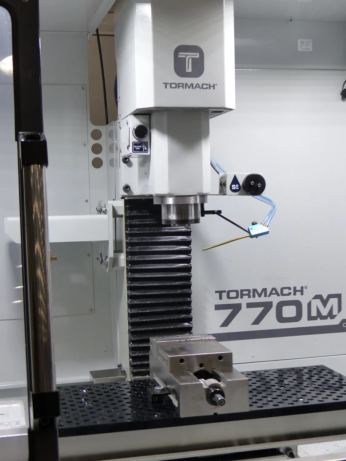 Wikimedia Commons・CNC Mill 1.jpg・CC BY-SA 4.0
01The three families
Every machining method can be sorted by what happens to the material: it is removed, it is deformed, or it is filled into a cavity. The three have completely different cost structures, and together with batch size they decide how the same part should be made.
| Family | Typical processes | Up-front cost | Cost per piece | Suits batches of |
|---|---|---|---|---|
| Cutting (removal) | Milling, turning, drilling, grinding, EDM | Low (fixtures) | High | 1 to a few thousand |
| Forming (deformation) | Stamping, bending, forging, drawing, rolling | High (tooling) | Very low | Thousands upward |
| Moulding (filling) | Injection moulding, die casting, powder metallurgy | Very high (tooling) | Very low | Tens of thousands |
02Cutting: accuracy comes from going slowly
Milling, turning, drilling and grinding are all cutting. What they share is removing material from a solid block, which gives the greatest freedom of shape and the best accuracy at the cost of poor material utilisation and long cycle times.
The ladder of operations and accuracy
| Operations | Typical tolerance | Typical Ra | What it asks |
|---|---|---|---|
| Rough milling / turning | ±0.2 mm | 6.3~12.5 | Leaves stock, aims at removal rate |
| Finish milling / turning | ±0.05 mm | 1.6~3.2 | Final cut for ordinary fitting surfaces |
| Reaming / boring | IT7 (±0.01 class) | 0.8~1.6 | Hole accuracy and cylindricity |
| Surface / cylindrical grinding | IT5~IT6 | 0.2~0.8 | Hard material, finishing after heat treatment |
| Lapping / honing | IT4 and better | 0.05~0.2 | Sealing faces, gauges, cylinder bores |
Five-axis and mill-turn
Machining a complex part on three axes means several set-ups, and every re-fixturing introduces error that accumulates in the final position tolerance. Five-axis and mill-turn machines fold several operations into one set-up. That is not only faster, more importantly it removes the set-up error, which is why some geometric tolerances simply cannot be achieved on a three-axis machine.
03Forming: pay for the tooling once, then it is cheap
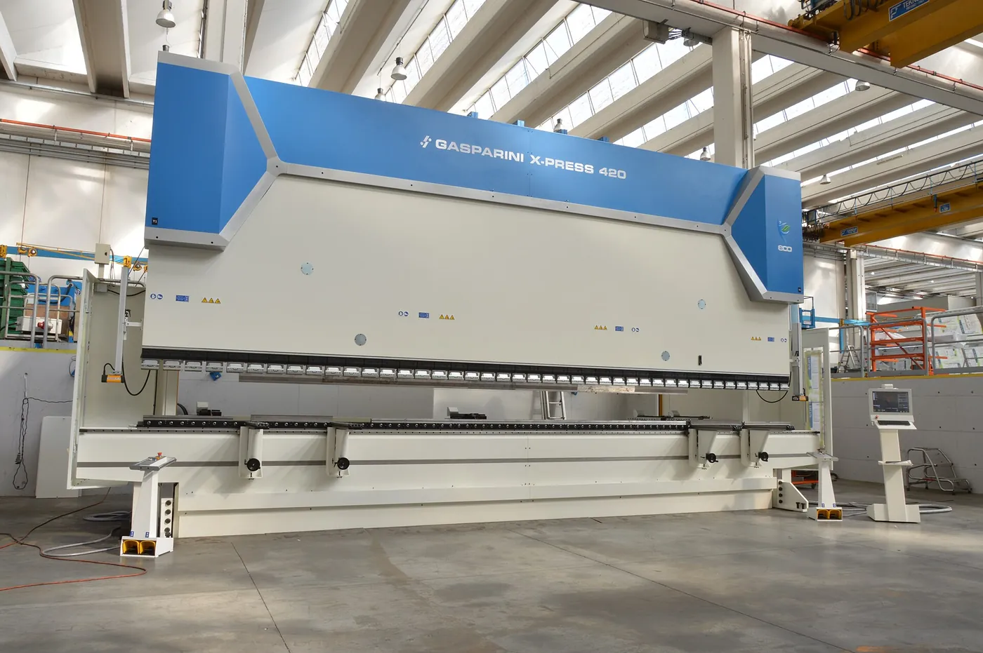
Stamping, bending, forging and drawing all deform material permanently without breaking it. Almost no material is wasted and cycle times are measured in seconds; the price is the tooling you must build first.
Sheet-metal clues on the drawing
- Uniform thickness. The whole drawing carries one thickness dimension; everything else is outline and hole positions.
- Bend lines and bend radii. Too small a radius cracks; the usual floor is one material thickness for soft material and two for hard.
- Flat pattern or developed length. Some customers supply the developed length; sometimes you must work it out.
- Distance from hole to bend line. A hole too close to a bend distorts when formed; the usual requirement is more than 2.5 times thickness plus the radius.
What a forging looks like on paper
A forging carries obvious draft angles (usually 3° to 7°), a parting line and machining allowance. Where the drawing shows two outlines, the forged profile and the machined profile, it is telling you which faces get machined and how much stock is left.
04Moulding: wall thickness decides everything
Injection moulding covers plastics and some metal powders. The clues on the drawing are unmistakable: uniform wall thickness, draft angles, ribs, and notes on gate and ejector pin positions.
| Design item | Usual guidance | What happens if you ignore it |
|---|---|---|
| Wall thickness | Uniform, varying by no more than 25% | Shrinkage, sink marks, internal stress |
| Rib thickness | 50–60% of the main wall | Sink marks at the rib root |
| Draft angle | 0.5°–2° per side | Scuffing on ejection, stress whitening |
| Corner radii | Not less than half the wall thickness | Stress concentration, cracking |
| Gate position | Feed into the thick section, away from cosmetic faces | Short shots, flow marks, weld lines |
05Six places on the drawing that decide the cost
- Tolerance grade. A general tolerance (ISO 2768-m) and an individually called-out IT7 are two different processes.
- Surface finish. Ra 3.2 comes off a single milling pass; Ra 0.4 almost always means grinding.
- Geometric tolerance. Position Ø0.05 may mean the whole feature has to be finished in one set-up.
- Material. SUS304 machines far worse than S45C; tool life and cycle time both change.
- Heat treatment. Placing it before or after finishing reorders the whole routing, and the distortion it causes has to be allowed for as stock on the drawing.
- Surface treatment. Anodising, zinc plating and blackening all change dimensions. If the drawing does not say whether measurement is before or after treatment, there will be an argument at acceptance.